
Haptic constants and primitives are defined by the vibrator HAL and mapped by the Android framework to public APIs. Perform these checks to determine if your device meets the minimum requirements to implement haptics:
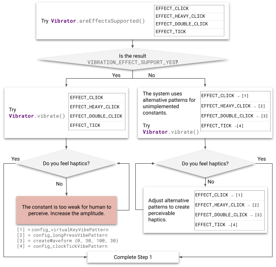
Figure 2. Implementing effects
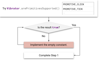
Figure 3. Implementing primitives
Implement constants
Haptic constants in VibrationEffect can be used by developers through VibrationEffect.createPredefined(). Check the implementation status of the following haptic constants.
| Haptic constants | Locations and summaries |
|---|---|
EFFECT_TICK, EFFECT_CLICK,
EFFECT_HEAVY_CLICK,
EFFECT_DOUBLE_CLICK |
VibrationEffect
classHaptic constants in VibrationEffect don't include any
notion of input events, and have no UI elements. Constants include the
notion of energy levels instead, such as EFFECT_CLICK and
EFFECT_HEAVY_CLICK, which are called by
createPredefined(). |
The alternative vibrations described next are performed on devices that don't
implement the VibrationEffect constants. Updating these configurations to
perform best on such devices is recommended.
EFFECT_CLICKWaveform vibration created with
VibrationEffect.createWaveformand the timings configured atframeworks/base/core/res/res/values/config.xml##config_virtualKeyVibePattern.EFFECT_HEAVY_CLICKWaveform vibration created with
VibrationEffect.createWaveformand the timings configured atframeworks/base/core/res/res/values/config.xml##config_longPressVibePattern.EFFECT_DOUBLE_CLICK
Waveform vibration created with
VibrationEffect.createWaveformand the timings (0, 30, 100, 30).EFFECT_TICKWaveform vibration created with
VibrationEffect.createWaveformand the timings configured atframeworks/base/core/res/res/values/config.xml##config_clockTickVibePattern.
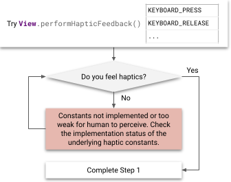
Figure 4. Implementing feedback constants
Haptic constants in HapticFeedbackConstants can be used by developers through View.performHapticFeedback()). Check the status of the following public feedback constants.
| Haptic constants | Locations and summaries |
|---|---|
CLOCK_TICK, CONTEXT_CLICK, KEYBOARD_PRESS,
KEYBOARD_RELEASE, KEYBOARD_TAP, LONG_PRESS,
TEXT_HANDLE_MOVE, VIRTUAL_KEY,
VIRTUAL_KEY_RELEASE, CONFIRM, REJECT,
GESTURE_START, GESTURE_END |
HapticFeedbackConstants classHaptic constants in HapticFeedbackConstants assist input events
with certain UI elements, such as KEYBOARD_PRESS and
KEYBOARD_RELEASE, which are called by
performHapticFeedback(). |
Implement primitives
Haptic primitives in
VibrationEffect.Composition
have scalable intensity that developers can use through
addPrimitive(int primitiveId, float scale, int delay).
The primitives can be divided into two categories:
Short primitives: Primitives with short duration, usually less than 20 ms. These are
CLICK,TICKandLOW_TICK.Chirp primitives: Primitives with varying amplitude and frequency, usually with a longer duration than short primitives. These are
SLOW_RISE,QUICK_RISE,QUCK_FALL,THUD, andSPIN.
Short primitives
Short primitives can be described by the vibrator motor output acceleration profile. The absolute frequency used varies for each primitive, depending on the actuator's resonant frequency. See Set up the testing equipment for more information about hardware setup and tools for measuring the output.
A valuable quality metric for short vibrations is the pulse to ring ratio (PRR), shown in Figure 5. PRR is defined as the ratio between the main pulse, defined by the signal inside the duration window where the amplitude decreases to 10% of peak amplitude, and the ring pulse, defined by the signal where the amplitude decreases from 10% peak amplitude to less than 1% of the peak amplitude. The formula for PRR is:
For more information on PRR, see Analyze the waveform and for more information on analyzing and comparing results, see Compare results using the performance map.
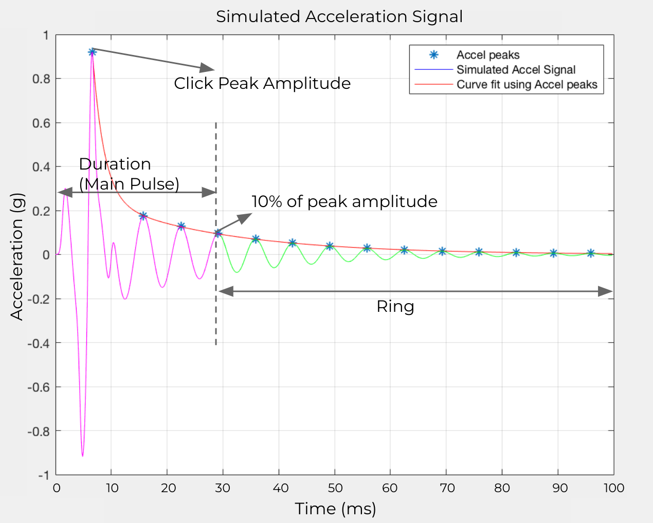
Figure 5. Pulse to ring ratio definition
Apply short primitives as a user input feedback or played in longer compositions to create soft textures. This means that they are usually triggered frequently and played in quick succession. The perceived intensity of a single short primitive can compound the larger effect intensity. For this reason, calibrate a single tick or low tick primitive with a larger composition, for example, 100 consecutive ticks.
Click primitive
The click primitive is a strong, crisp effect usually operating close to a device's resonant frequency to reach maximum output in a short duration. It's stronger and deeper than the other primitives, performing at maximum intensity.
If available, use motor overdrive at the beginning and active braking at the end to achieve a short motor rise and fall time. For some motors, using a square wave instead of sine wave can achieve faster acceleration. Figure 6 shows an example output acceleration profile for the click primitive:
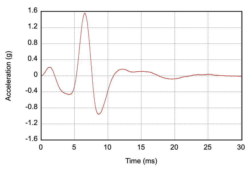
Figure 6. Example of output acceleration profile for click primitive
| Parameter | Guideline |
|---|---|
| Duration |
Target: 12 ms Limit: < 30 ms |
| Peak output acceleration |
Target: 2 G Limit: > 1 G |
| Frequency | Roughly at resonant frequency |
Tick primitive (light tick)
The tick primitive is a sharp, short effect usually operating at a higher frequency range. This primitive can also be described as a medium intensity click at a higher frequency with a short tail. The same guidance applies for achieving a short rise time using motor overdrive or a square wave for the initial onset, and active braking at offset. Figure 7 shows an example output acceleration profile for the tick primitive:
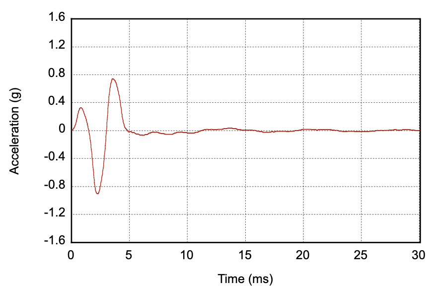
Figure 7. Example of output acceleration profile for tick primitive
| Parameter | Guideline |
|---|---|
| Duration |
Target: 5 ms Limit: < 20 ms |
| Peak output acceleration |
Target: Half of Limit: Between 0.5 G and 1 G |
| Frequency |
Target: 2x resonant frequency Limit: < 500 Hz |
Low tick primitive
The low tick primitive is a softer, weaker version of a light tick, operating at a lower frequency range to provide more body to the effect. This primitive can also be described as a medium intensity click at a lower frequency, intended to be used repetitively for dynamic feedback. The same guidance applies for achieving a short rise time using motor overdrive or a square wave for the initial onset. Figure 8 shows an example output acceleration profile for the low tick primitive:
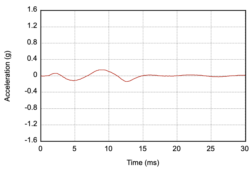
Figure 8. Example of output acceleration profile for low tick primitive
| Parameter | Guideline |
|---|---|
| Duration |
Target: 12 ms Limit: < 30 ms |
| Peak output acceleration |
Target: 1/4 of a Limit: Between 0.2 G and 0.5 G |
| Frequency |
Target: 2/3 resonant frequency Limit: < 100 Hz |
Chirp primitives
Chirp primitives can be described by the input signals for voltage level and vibration frequency. The acceleration that the motor is able to output at different frequency ranges varies depending on the frequency response curve of the actuator. The frequency ranges and voltage levels need to be adjusted on a per device basis.
Slow rise primitive
The slow rise is a slow amplitude and frequency sweep upward with soft onset and consistently increasing vibration intensity across the sweep. It can be implemented by a consistent sweep of both the amplitude and frequency, using a lower frequency range that operates off resonance. Figure 9 shows the input parameters and an example output acceleration profile for this implementation. (The red line matches the amplitude labels on the left and represent how the vibration amplitude varies with time. The blue line matches the frequency labels on the right and represent how vibration frequency varies with time.)
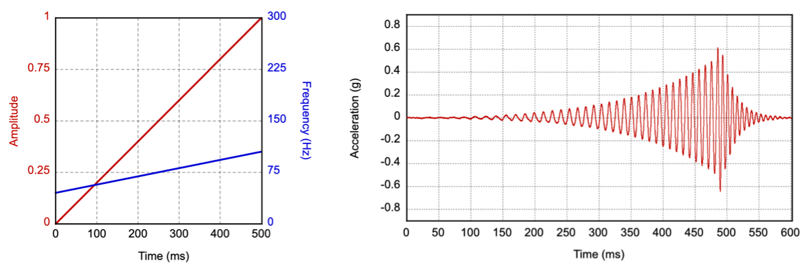
Figure 9. Input parameters and example of output acceleration profile for slow rise primitive
If the frequency response of the motor is limited (not strong enough off of its resonant frequency) then an alternative implementation is a sine sweep from 1/2x to 1x the resonant frequency. The motor resonance contributes to reaching the signal peak at the end.
| Parameter | Guideline |
|---|---|
| Duration |
Target: 500 ms Tolerance: 20 ms |
| Peak output acceleration |
Target: 0.5 G Limit: Between 0.5 G and 1 G |
| Frequency |
Target: 1/2 to 2/3 of resonant frequency Alternative: 1/2 to resonant frequency |
Quick rise primitive
The quick rise is a faster amplitude and frequency sweep upward with soft onset and consistently increasing vibration intensity across the sweep. The output acceleration and vibration frequency targets should be the same as the slow rise primitive, achieved in a shorter duration. Figure 10 shows the vibration input parameters and an example output acceleration profile for the slow rise primitive. (The red line matches the amplitude labels on the left and represent how the vibration amplitude varies with time. The blue line matches the frequency labels on the right and represent how vibration frequency varies with time.)
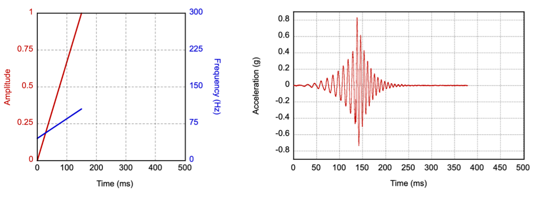
Figure 10. Input parameters and example of output acceleration profile for quick rise primitive
| Parameter | Guideline |
|---|---|
| Duration |
Target: 150 ms Tolerance: 20 ms |
| Peak output acceleration |
Target: Same as Limit: Same as |
| Frequency |
Target: Same as Alternative: Same as |
Quick fall primitive
The quick fall is a fast amplitude and frequency downward sweep with a soft onset. You can use a higher frequency as the start point while the motor is ramping up to reach the peak output acceleration. The frequency should be consistently decreasing across the sweep, even during the rise time. Figure 11 shows the input parameters and an example output acceleration profile for this implementation. (The red line matches the amplitude labels on the left and represent how the vibration amplitude varies with time. The blue line matches the frequency labels on the right and represent how vibration frequency varies with time.)
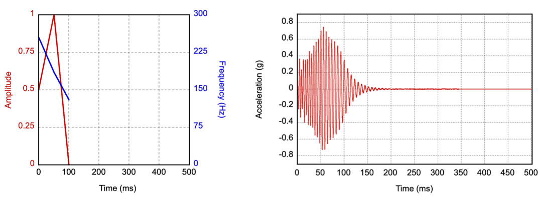
Figure 11. Input parameters and example of output acceleration profile for quick fall primitive
| Parameter | Guideline |
|---|---|
| Duration |
Target: 100 ms Tolerance: 20 ms |
| Peak output acceleration |
Target: 1 G Limit: Between 0.5 G and 2 G |
| Frequency |
Target: 2x to 1x the resonant frequency |
Thud primitive
The thud is a thumpy, low, percussive effect that simulates the physical sensation of knocking on hollow wood. This primitive operates in a low frequency range, similar to the low tick primitive, to provide more body to the effect. You can implement the thud primitive as an amplitude and frequency downward sweep at a lower frequency range (preferably less than 100 Hz). Figure 12 shows the input parameters and an example output acceleration profile for this implementation. (The red line matches the amplitude labels on the left and represent how the vibration amplitude varies with time. The blue line matches the frequency labels on the right and represent how vibration frequency varies with time.)
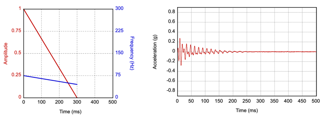
Figure 12. Input parameters and example of output acceleration profile for thud primitive
If the frequency response of the motor is limited then an alternative implementation is to start with a full intensity drive signal at the resonant frequency and drop to the lowest possible frequency that can still be perceived. This approach might require an increase of the drive signal intensity at the lower frequency for vibration to be felt.
| Parameter | Guideline |
|---|---|
| Duration |
Target: 300 ms Tolerance: 20 ms |
| Peak output acceleration |
Target: 0.25 G Limit: Between 0.2 G and 0.5 G |
| Frequency |
Target: 1/2 to 1/3 of resonant frequency Alternative: 1x to 1/2 of resonant frequency |
Spin primitive
The spin simulates a spinning momentum of fast up and down spin with a slight accent at the center. The spin can be implemented by sweeping the amplitude and frequency independently, in opposite directions and followed by the reverse motion. It's important to use a lower frequency range (preferably less than 100 Hz). Figure 13 shows the input parameters and an example output acceleration profile for this implementation. (The red line matches the amplitude labels on the left and represent how the vibration amplitude varies with time. The blue line matches the frequency labels on the right and represent how vibration frequency varies with time.)
We recommended that the spin primitive is called twice in succession, or three times in compositions, to achieve a spinning and unsteady sensation.
If the frequency response of the motor is limited, an alternative implementation is to do a rapid sine sweep from 1/2x to 1x the resonant frequency and back. The motor resonance automatically gives the signal an accent in the middle.
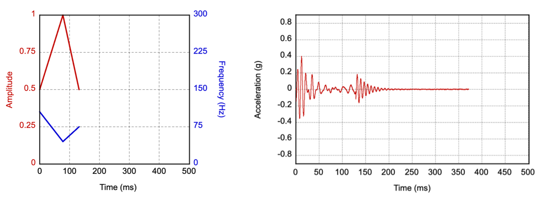
Figure 13. Input parameters and example of output acceleration profile for spin primitive
| Parameter | Guideline |
|---|---|
| Duration |
Target: 150 ms Tolerance: 20 ms |
| Peak output acceleration |
Target: 0.5 G Limit: Between 0.25 G and 0.75 G |
| Frequency |
Target: 2/3 to 1/3, then back to 1/2 of resonant frequency Alternative: 2/3 to 1x, then back to 1/2 of resonant frequency |