
Android 17 introduces CTS Verifier tests for audio multi-channel input and output.
This page outlines the setup and verification steps for 4-channel input and 8-channel output audio testing in the CTS Verifier.
Test 4-channel input ([5.6/H-1-11])
This test verifies the device can capture four discrete channels.
Calibrate and set up hardware
To set up the hardware for testing, loop each of the four output channels generated by the CTS Verifier test back into the corresponding input channels on the Zoom AMS-44. Because the Zoom AMS-44 provides stereo outputs A and B, which carry channels 1/2 and 3/4 respectively, you need Y-cables to split these stereo signals back into individual mono inputs.
Recommended hardware and cables
We recommend using one of these audio interfaces for testing:
Option 1: Zoom AMS-44: 4-in/4-out professional interface
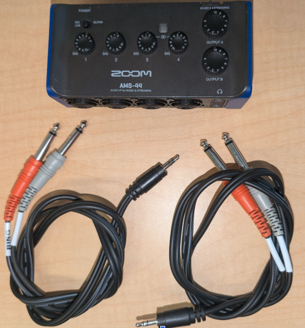
Figure 1. Zoom AMS-44 and cables.
Option 2: Focusrite Scarlett 4i4 (4th Gen): 4-in/4-out professional interface
Set up physical connections
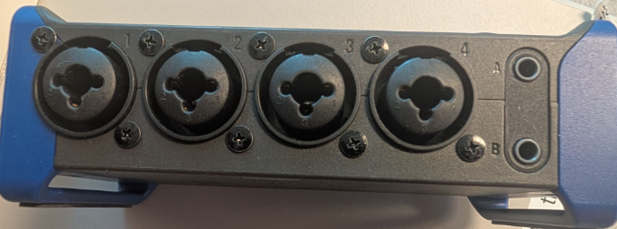
Figure 2. Zoom AMS-44 inputs and outputs.
Connect output A to inputs 1 and 2:
- Plug one 3.5 mm stereo end of a Y-cable into the output A jack on the front of the Zoom AMS-44.
- Connect the mono 6.5 mm plug corresponding to the left channel of output A to the input 1 jack on the AMS-44.
- Connect the mono 6.5 mm plug corresponding to the right channel of output A to the input 2 jack on the AMS-44.
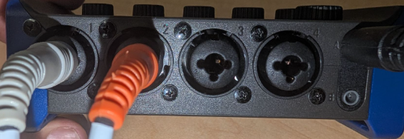
Figure 3. Zoom AMS-44 Zoom AMS-44 output A connections.
Connect output B to inputs 3 and 4:
- Plug the 3.5 mm stereo end of the second Y-cable into the output B jack on the front of the Zoom AMS-44.
- Connect the mono 6.5 mm plug for the left channel of output B to the input 3 jack.
- Connect the mono 6.5 mm plug for the right channel of output B to the input 4 jack.
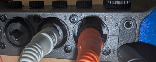
Figure 4. Zoom AMS-44 Zoom AMS-44 output B connections.
Connect the Zoom AMS-44 to your Android device under test (DUT) using a USB cable.
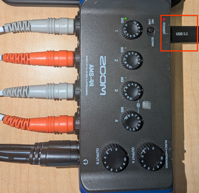
Figure 5. Connect Zoom AMS-44 to DUT with USB.
Configure the Zoom AMS-44
- Set the LOOPBACK switch on the Zoom AMS-44 to OFF. This is crucial because the AMS-44's internal loopback feature downmixes all inputs, which prevents the CTS Verifier from testing individual channels.
Set the DIRECT MONITOR switch on the Zoom AMS-44 to OFF.
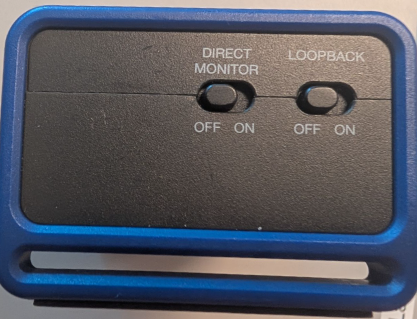
Figure 6. Zoom AMS-44 direct monitoring and loopback switches.
Set the individual gain knobs for inputs 1, 2, 3, and 4 to a low to mid-range level. You adjust these during calibration.
Set output A and B volume on the Zoom AMS-44 to maximum.
Set the DUT's volume to mid-range. You can change this during calibration to achieve optimal signal quality.
Calibration procedure using CTS Verifier
- On the Android DUT, launch CTS Verifier and navigate to Audio > Audio Data Paths USB 4-Channel Input Test.
- Connect the Zoom AMS-44 by USB. The test screen should show InCh: 4, OutCh: 4, indicating the device is recognized.
- Tap the Calibrate button within the test. This opens a calibration dialog with an oscilloscope display.
The calibration utility plays a sine wave sequentially through each of the four logical output channels (channel 1 through channel 4). For each step:
Channel 1 (output A left -> input 1): When the utility indicates channel 1 is active, adjust the Gain 1 knob on the Zoom AMS-44. Observe the oscilloscope. You see a clean sine wave. Adjust the gain until the peak amplitude is around 0.8 on the display. The green SIG indicator is active.
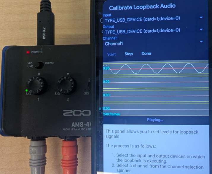
Figure 7. Zoom AMS-44 calibration procedure.
Channel 2 (output A right -> input 2): When channel 2 is active, adjust the Gain 2 knob on the AMS-44 to achieve a similar amplitude (around 0.8) on the oscilloscope.
Channel 3 (output B left -> input 3): When channel 3 is active, adjust the Gain 3 knob.
Channel 4 (output B right -> input 4): When channel 4 is active, adjust the Gain 4 knob.
Repeat adjustments as needed until all four channels show a strong, clean sine wave (around 0.8 peak amplitude) when selected in the calibration dialog.
Run the 4-channel input test
- Exit the calibration dialog.
Tap Start on Audio Data Paths USB 4-Channel Input Test.
The test automatically cycles through playing a tone on each output channel and verifying the signal on the corresponding input.
Monitor the oscilloscope within the test for each channel (Ch 0 to 3).
The test passes if all four channels show a high magnitude and low jitter, indicating successful loopback and capture of each discrete channel.
8-channel output testing ([5.6/H-1-10])
This test verifies support for Quad, 5.1, and 7.1 output channel masks. Eight-channel input isn't required; the eight outputs are mixed back into a stereo input for verification.
Recommended hardware
Vantec USB external 7.1 channel audio adapter: A common, class-compliant adapter that natively reports Quad, 5.1, and 7.1 output masks
One of these stereo audio mixers:
- Option 1: One of these 6-way stereo audio mixers:
- 6-way stereo audio mixer (on Ebay)
- 6-way stereo audio mixer (on AliExpress)
- 6-way stereo audio mixer (on Amazon)
- Power supply requirements for the active mixer:
- Consult the specifications of your purchased mixer model. In general, active mixers require a 5 V to 24 VDC (commonly 12 VDC, >= 500 mA) power supply with a standard 5.5 mm OD x 2.1 mm ID center-positive barrel connector.
- Suggested search query for replacement power supplies: "12V DC power supply 5.5mm x 2.1mm barrel connector center positive"
- Example power supply links:
- Option 2: Cubilux 4-channel audio switcher
- Cubilux 4-channel audio switcher (on Amazon)
- Option 1: One of these 6-way stereo audio mixers:
Set up loopback mixing
You must mix the eight discrete outputs back into a stereo input, using one of these options:
Option 1 (active mixer - recommended): Use a 6-way stereo audio mixer:
- Connect the eight outputs from the Vantec adapter into the mixer inputs.
- The mixer combines these into a single stereo signal.
- Route the mixer's stereo output back into the Vantec adapter stereo input.
Option 2 (manual switcher): Use a device like the Cubilux 4-channel audio switcher. This provides high channel isolation but requires the tester to manually switch the active channel being routed back to the input.
Calibrate
- Use the CTS Verifier loopback calibration dialog to play each channel of the Quad, 5.1, or 7.1 mask individually.
- Verify that each discrete output channel is correctly mixed and captured by the input.
General calibration procedure
Connect the eight discrete output channels from the Vantec adapter to the inputs of your 6-way stereo audio mixer such that they're correctly summed into the mixer's stereo output, which is then looped back to the Vantec's stereo input. The test expects specific channels to appear on the left or right input of the Vantec.
Calibration procedure for audio data paths USB multichannel test hardware setup
- Connect the power adapter to the stereo audio mixer.
- Connect the Vantec USB 7.1 audio adapter to the DUT using a USB cable and OTG adapter if necessary.
- Connect the stereo output of the 6-way stereo audio mixer to the stereo line-in input of the Vantec USB adapter. Use a standard 3.5 mm Y stereo cable for this loopback. You might need to swap the left and right (white and red in Figure 8) cable position to correctly adjust the left and right channels, but can also do that during the later input connection step, when a signal is available.
Set the DUT's volume to about 90% of its maximum range. Use this setting, along with the mixer's individual gains, to achieve an optimal audio signal.
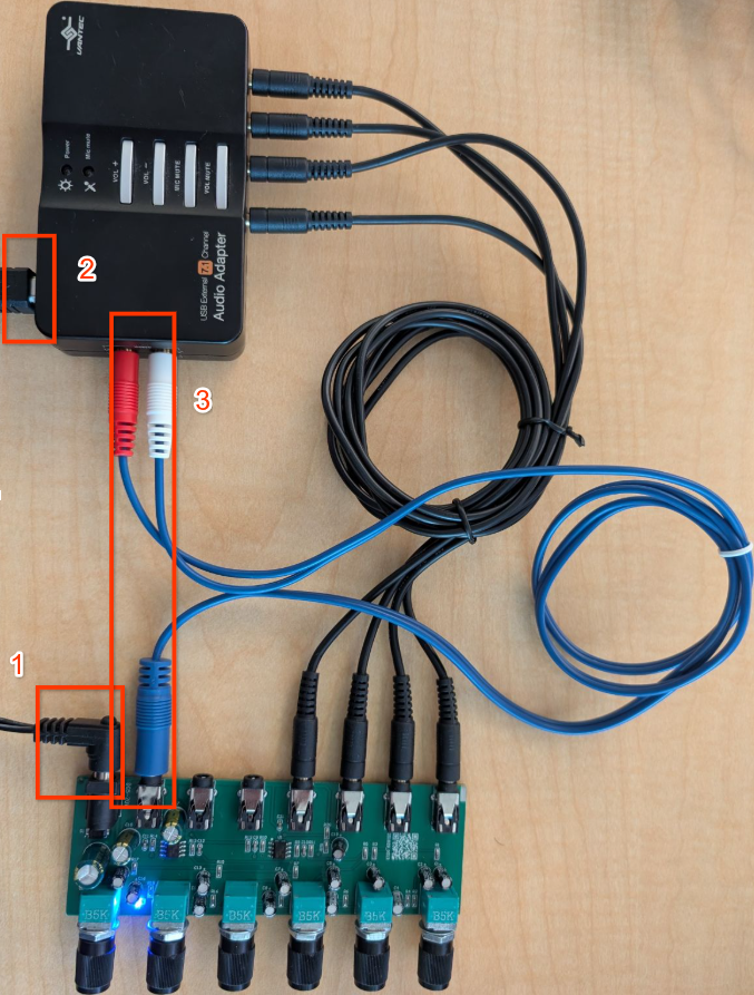
Figure 8. Connect mixer output to Vantec input.
Connect Vantec output to mixer input connections
The Vantec adapter has eight output channels, typically grouped into four 3.5mm stereo jacks: front (FL/FR), back (BL/BR), center/sub (FC/LFE), and side (SL/SR). You need to connect each of these 8 discrete outputs to the inputs of your 6-way stereo audio mixer.
Identify which physical connector on the Vantec correspond to each channel (for example, FL, FR). Refer to Vantec's documentation or labels. The 6-way stereo mixer lets you route each connected input to either its left or right stereo output bus.
Calibration steps
- On the Android device, open CTS Verifier and select Audio Data Paths USB Multichannel Test.
Tap Calibrate.
The calibration dialog plays a test tone through each of the eight channels, the channel selection has the following order:
AudioFormat.CHANNEL_OUT_FRONT_LEFT (FL)
AudioFormat.CHANNEL_OUT_FRONT_RIGHT (FR)
AudioFormat.CHANNEL_OUT_BACK_LEFT (BL)
AudioFormat.CHANNEL_OUT_BACK_RIGHT (BR)
AudioFormat.CHANNEL_OUT_FRONT_CENTER (FC)
AudioFormat.CHANNEL_OUT_LOW_FREQUENCY (LFE)
AudioFormat.CHANNEL_OUT_SIDE_LEFT (SL)
AudioFormat.CHANNEL_OUT_SIDE_RIGHT (SR)
Verify and adjust
Do the following for each channel as it is played:
- Note which channel is currently active in the calibration dialog.
- Confirm the signal is correctly passing from the Vantec output through the mixer and back to the Vantec's input. You should see a signal in the calibration oscilloscope.
- When FL, BL, FC, or SL is active, verify that a signal registers on the left channel of the calibration display.
- When FR, BR, LFE, or SR is active, verify that a signal registers on the right channel of the calibration display.
Use the individual gain or volume knob on the Stereo Audio Mixer that controls the input connected to the playing Vantec output channel. Adjust the gain until the calibration display shows approximately 0.8 gain for that channel.
Continue this process for all eight channels. Keep track of which mixer knob adjusts which Vantec channel.
After all eight channels have been played and calibrated to a gain of approximately 0.8 or higher, exit the calibration dialog.
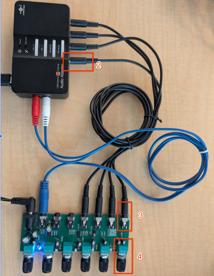
Figure 9. Connect Vantec output to mixer input.
Run the 8-channel output test
- Navigate to Audio > Audio Data Paths USB Multichannel Test in the CTS Verifier.
Connect the Vantec USB audio adapter and the mixer or switcher setup.
Active mixer
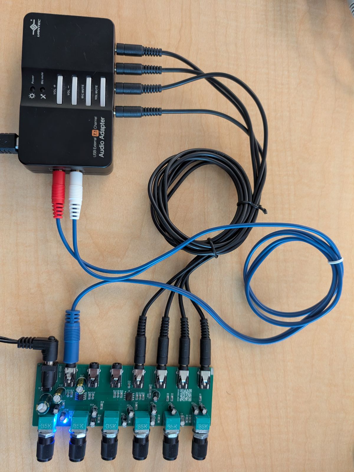
Figure 10. Active mixer connection.
Manual Mixer
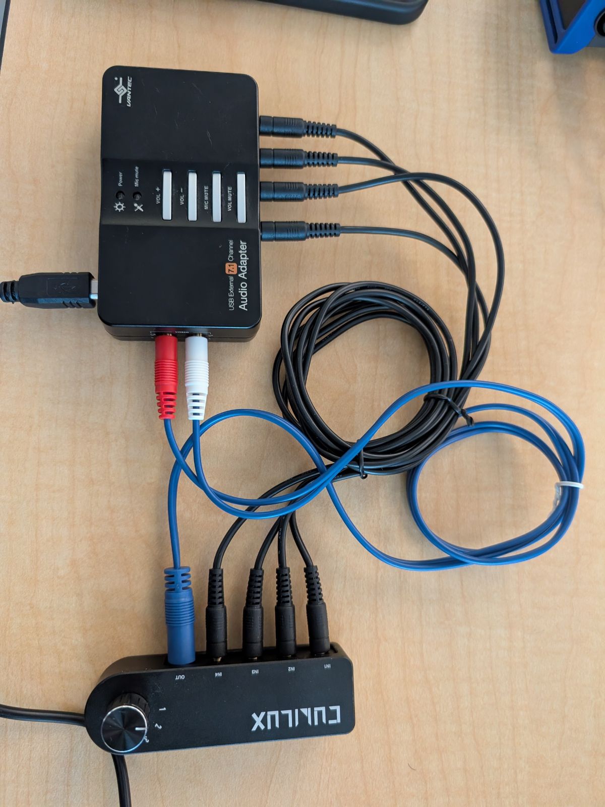
Figure 11. Manual mixer connection.
Optional: If you're using a manual switcher (option 2), check the Manual Mode box. This lets you manually route the specific channel being tested to the stereo input before starting each sub-test.
Press Start.
The test iterates through all channels in the following masks:
- Quad: front left, front right, back left, back right.
- 5.1: front left, front right, center, LFE, back left, back right.
- 7.1: front left, front right, center, LFE, back left, back right, side left, side right.
The analyzer expects odd-indexed channels (L, C, LB, SL) to appear on the left input and even-indexed channels (R, LFE, RB, SR) to appear on the right input.
Verify each channel passes by checking for a clean signal in the oscilloscope.
The test passes if all masks (Quad, 5.1, 7.1) are fully validated.